17XT/18XT Front LINKAGES
My first project on the team as a freshman mechanical engineer was to design the front linkages for the 17XT. Then, while I became the Suspension Lead Engineer for the 18XT, due to team bandwidth issues I got the chance to redesign it. Thus, I like to include this as a case study of my growth as an engineer.
17XT OVERVIEW
Compared to previous linkages, the installation ratio had gone down significantly, placing the shock-mounted linkage into significantly more bending. Furthermore, the previous year had used extremely large rod ends placed in bending, which was poor design practice. The previous year's lower linkage also included an out-of-plane tube which markedly increased manufacturing time.
The improvements I made were to design a custom insert for a ball joint, and extend the insert-tube back to the shock/damper mounting to provide the most moment of inertia for the bending moment. Furthermore, I brought the lower linkage to a completely planar design, which reduced manufacturing time. I also optimized the insert to improve weldability and ensure the proper penetration was reached.

Above: 17XT Front Lower Linkage (all 0.035" CRS 4130)
Below: 17XT Front Upper Linkage (all 0.035" CRS 4130)

When tested the first time, the upper linkage failed in bending. Due to time constraints, the tube thicknesses were all modified to 0.095", significantly increasing component weight. The lack of validated analysis had significantly hurt this design, and this is the reason I significantly overhauled component qualification the following year.
18XT OVERVIEW
First, I took data from a wheel force transducer, which obtains all three forces and moments at a vehicle's hub. Drive day data was taken under competition-like scenarios to capture our maximum expected load scenario. I processed this data, using a Savitsky-Golay filter to remove signal noise, and determined our maximum load from our linkages to be 10% higher than expected.
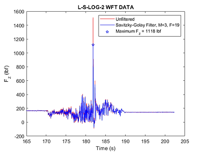

With loads now confidently enveloped, I realized that the bending load was the driving force, and the tensile/compressive loads were minimal.
Therefore, I designed the following upper linkage with a thick-wall square tube to maximize the moment of inertia, while dropping the "A-tubes" to 0.049." Furthermore, the cross-bracing tube was changed to a plate. Overall, the design was far more optimized for the expected loads.
To validate the analysis, I ran a validation test using a mass and dial indicator, and compared the results to those measured in the finite element model. After improving the model, I got to within 12% of the measured deflection. As a result, I was now confident that the component was qualified.
Overall, the overall component weight reduced by 31% (1.05 lbm), with all design margins met. No failures were recorded during the season.


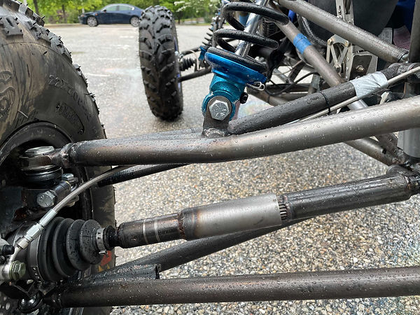
Above: 18XT Front Upper Linkage
Below: 18XT Front Lower Linkage
